The new tunnel connection being opened in The Hague is claimed to be the most sustainable tunnel in the Netherlands.
The tunnel gets its rather unusual name from an artwork by Dutch painter Piet Mondrian, the Victory Boogie Woogie.
The construction of the new tunnel project is being headed by BAM Infra, which is meeting tough environmental constraints set by the Netherlands Government. The Rotterdamsebaan project, as it is known, involves building the new road for the City of The Hague, which includes the construction of the tunnel.
The project to build this new road and tunnel connection is necessary to tackle the heavy traffic congestion in the area. At present, vehicles travelling to and from The Hague rely on a number of routes, one of which is the Utrechtsebaan (A12). This carries around 40% of the traffic entering and leaving the city and has suffered from severe congestion, particularly at peak periods. The traffic congestion also affects residential areas such as Rijswijk and Voorburg in The Hague as well as surrounding areas.
However, opening the Rotterdamsebaan link, measuring around 4km in all, will help to address the traffic problem. It will make The Hague and the area surrounding it more accessible according to the project partners.
The Rotterdamsebaan will connect the A4 and A13 highways, as well as the city’s central ring road. It runs from the Ypenburg interchange, entering a cutting in the Vlietzone and then going underground close to the car park at Drievliet. The underground section of the Rotterdamsebaan runs under the Westvlietweg, Voorburg-West, the Forum Hadriani archaeological site and the Binckhorst harbour. The road then re-emerges at Binckhorst by the Zonweg, where it links with the Binckhorstlaan and the Mercuriusweg. The tunnel has been designed for vehicles to travel at speeds of up to 70km/h.
BAM Infra is building the Rotterdamsebaan road project at a cost of some €301 million. The link will includes two 450m-long ramps, 650m of cut and cover tunnel and the dual tunnel sections that have been bored with the help of a massive TBM.
A key improvement will be the reduction in heavy vehicles using minor roads in the area. Overall, the opening of the road and tunnel stretch will help to distribute vehicle traffic more evenly, while reducing vehicle movements on minor roads as well as for the existing (and overloaded) Utrechtsebaan. For drivers, the congestion problem will be reduced significantly and journey times will be shorter. From a safety perspective, a better distribution of the vehicle traffic to the new tunnel will reduce risks for vulnerable road users such as cyclists and pedestrians along the minor roads.
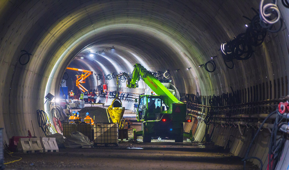
Under construction
The tender process was from 2014 to 2015, with BAM Infra winning the deal and commencing its preparatory work in 2015. Conventional earthmoving techniques were used to remove material for the ramp sections and the cut and cover tunnel stretches.
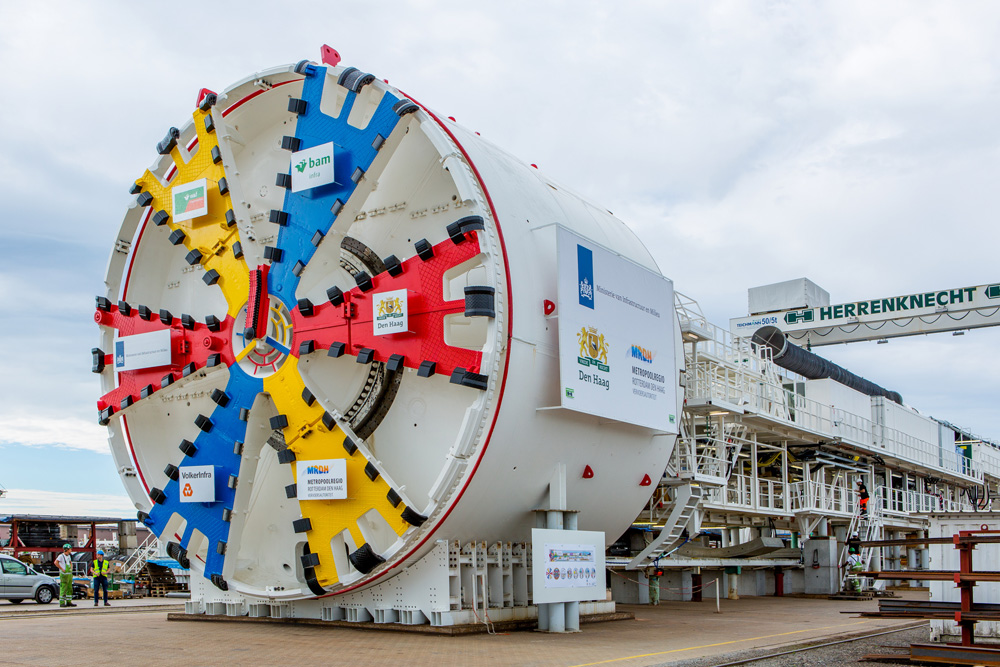
The bored tunnel sections were driven using a tunnel boring machine (TBM) built by German specialist Herrenknecht. For the project the TBM was named the Catherina-Amalia.
The machine was equipped with a mixed shield with a diameter of 11.34m, driving both of the 1.6km-long twin tubes within a 12-month period. However, the work was challenging, not the least of which was due to the facts that the site area was cramped and that the team had to ensure traffic flow continued during construction.
The project partners, however, had experience of the conditions, having previously carried out tunnelling work in the area between 2013 and 2015. The same TBM had been used to drive the Sluiskil Tunnel between Goes and Ghent, which opened to traffic in May 2015. This link also features twin tubes and measures around 1.6km in length, while it was built to reduce the congestion problems over the existing Sluiskil Bridge. After the TBM carried out the Sluiskil Tunnel work, the machine was returned to the Herrenknecht plant in Kehl, Germany to be refurbished and made ready for its next contract.
Work to drive the first bore of the Victory Boogie Woogie Tunnel was carried out between January and July 2018. Weighing 1,600tonnes and measuring 80m long, the TBM then had to be disassembled and moved into position for the second drive. Although complex, this process was carried out within schedule and the TBM was then able to bore the second tube, having started with this portion of the work in September 2018. The TBM used was named for the work and finished its second drive on the 10th of January 2019 to complete its work for the Victory Boogie Woogie Tunnel.
In all, the 80m-long TBM excavated over 330,872m3 of material and at the deepest point, the tunnels are 31m below ground. Driving the Victory Boogie Woogie Tunnel, the TBM proved highly productive and Herrenknecht said that the machine was able to achieve advance rates of up to 30m/day at one point during its second drive.
As with the Sluiskil Tunnel, the ground conditions for the Victory Boogie Woogie Tunnel proved difficult, featuring sand, silt and clogging-prone clay.
However, the previous experience with the Sluiskill Tunnel meant that the TBM could be configured specifically to cope with the conditions. It was fitted with an open cutting face, featuring direct material transport from the centre as well as a specially adapted slurry circuit.
Once the twin tube link had been driven, the sides of the Victory Boogie Woogie Tunnel were supported using precast segments. One of the tunnels has 818 complete ring sections while the other has 820 ring sections. Each ring itself is made up of eight components, so the longer of the tunnels features 6,650 of these precast units while the other tunnel has 6,544 of the components. When the lining work had been completed, it allowed the roadbed to be built featuring two lanes in either tube. In addition, cross tunnel connections were constructed at 250m intervals to link the twin tubes, intended to boost safety as well as provide maintenance access.
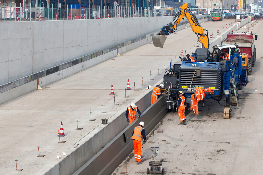
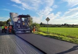
The roadway for both tunnels has been constructed on a concrete bed with an asphalt running surface, allowing a maximum height clearance of 4.7m.
Clean route
The project has had to meet tough environmental requirements and for this reason, a number of sustainable solutions are being utilised for the tunnel. The impact of work to build the project has been reduced by minimising construction traffic movements as well as by building a temporary road link.
The visual impact of the portal in the Vlietzone has been taken into account, with its design intended to ‘fit in with the green landscape of the area’.
The environmental solutions include the installation of solar panels that provide all of the electrical power needed for the control room of the tunnel. Low energy LED lighting is used, reducing the power required and also minimising the need for long-term maintenance, given the longevity of the units. The systems also include a fine dust reduction system (FDRS) using filters installed at the tunnel portals to optimise the air quality within the link. The tunnel builders have fitted the FDRS to address the issue of particulates within the tunnel.
Meanwhile, the road surfaces are utilising a special LEAB grade of asphalt that features the use of RAP. Pumps are also installed inside the tunnel to remove rainwater, with this being passed through to the local sewer system for safe disposal.
Other sustainability measures used during the construction process have included the use of cleaner fuel grades onsite and the installation of sound diffraction equipment to minimise traffic noise transmission.
Lifting and Shifting
A huge challenge for the project came in the shape of the massive TBM itself. Because of the TBM’s sheer scale Sarens, a specialist in lifting and shifting, was brought in to move the machine. This was a key role for the entire tunnel boring operation and Sarens carried out the work on behalf of its client Combinatie Rotterdamsebaan.
Together with Herrenknecht, the firm was tasked with the initial transport and assembly of the TBM to the construction site. The firm needed to carry the TBM in 50 separate sections from the Herrenknecht factory in Germany to the site in the Netherlands, with the heaviest piece weighing some 130tonnes and measuring 5.7m wide by 4.4m high.
When the components arrived, the team started to assemble the TBM as well as the crawler crane needed for the initial lift. However, the space available for crane operation was limited so Sarens opted to use its LR1350-1 crane for its capacity and ability to manoeuvre in the tight space.
Due to the constricted working area, some parts of the tunnel boring machine had to be first assembled close to the launching shaft and then transported using self-propelled mobile transporters (SPMTs) to the crawler crane for the lift. The crew also used a second mobile crane for the installation of the back-up trailer.
Using a crew of 10 members at a time, Sarens carried out the lifts for the cutting head, 120tonne steel cylinder, and 70tonne pump station, which required two mobile cranes working in tandem.
Sarens also then had to transport the TBM components back to the launch shaft after it had been used to drive the first bore. After the TBM carried out boring of the second tunnel, Sarens once again disassembled the machine and transported it away from the site.
However, the second phase of the project in particular, to move the TBM back to the launch shaft after the first tunnel had been bored, was not without its challenges.
One of these challenges was that the last part of the TBM to be disassembled was also the first part required for reassembly. To ensure that the reassembly work did not affect the project timeline, the team from Sarens had to plan the entire transfer operation carefully to ensure each specific task was correctly scheduled.
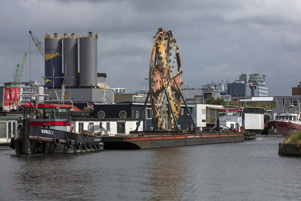
The actual size of the TBM was itself a challenge. While most of the TBM’s components were of a size that meant they could be moved by road, six were simply too large and heavy for this option. Instead, these sections had to be transferred using an SPMT as well as a barge.
The large SPMT featured no less than 24 axles, while the barge measured 45m long by 7m across the beam. Sarens also used a number of other large items of equipment to move the TBM components. These included a 350tonne capacity LR1350-1 crawler crane, a 700tonne capacity AC700 all-terrain crane, and two mobile cranes: an LTM1400-7.1 and an LTM1130-5.1.
The TBM’s cutting shield featured a diameter of 11.8m and its size meant that it was simply too wide to be moved along the roads or over bridges in the area. As a result, Sarens set up a support system that would allow the shield to be raised vertically. The crew then used the support system to lift the cutting shield in one piece, first to transfer it from the SPMTs to the barge, and then from the barge, back onto the SPMTs.
The barge had to make three trips along the canal to move the largest components. It was docked next to where a crane with a capacity of 700tonnes was located on a public road. The crane then transferred parts from the barge to the SPMTs for onward transport.


")